
S-LED-U: Ampio lighting bus voltage driver
S-LED-U
Tags:
- Access Control,
- Air conditioning,
- Ampio CAN modules,
- Ampio Cloud,
- Analogue control,
- Central heating,
- CON Family,
- Dali,
- Dallas 18B20,
- DIM Family,
- Dimmer,
- DIN Rail modules,
- Display,
- DOT Family,
- Hotel,
- IN Family,
- Input Modules,
- Integrations,
- IP,
- Junction Box modules,
- KNX,
- LED Family,
- LED lights,
- Lights,
- Mobile App,
- Modbus,
- Node-red,
- OC Family,
- Open Collector Drivers,
- OUT Family,
- Output modules,
- OWA Lighting,
- OWA lighting bus modules,
- RDN Family,
- REL Family,
- Relay Outputs,
- RFID,
- RGBW Lights,
- Roller shutters and blinds,
- RS-232,
- RS-485,
- SATEL,
- Security,
- SENS Family,
- Sensors,
- SERV family,
- Touch panels,
- Wall Switch
Technical data
Dimensions
Environment
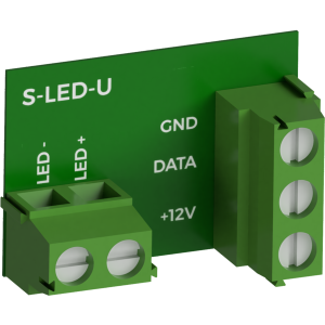
The image above is for illustration purpose only. The actual module may vary from the one presented here.
General features
Module S-LED-U is a component of the Ampio system. Required voltage to power the module is 11 — 24V DC. The module is controlled via OWA lighting bus.
The module acts as an OWA lighting bus node driver and allows for smooth brightness adjustment of voltage-controlled LED lighting with a maximum current consumption of 8A and a rated voltage not exceeding 40V.
OWA lighting bus
The OWA lighting bus (One Wire Ampio) is a solution dedicated to controlling LED lighting. Each bus segment contains a controller and up to 16 lighting node drivers or LED lamps with integrated drivers. From the controller level, it is possible to smoothly adjust the brightness of light sources connected to each of the controllers. It is possible to control sets of light points or individual lights independently. It is also possible to implement the so-called staircase effect, i.e. smooth brightening and dimming of consecutive light points along the stairs, driveway, etc.
The OWA lighting bus consists of two wires – a ground wire and a wire that ensures communication between the controller and the drivers of a lighting node. Lighting node drivers also require a power line, hence the OWA bus is usually run with a three-wire cable.
With the use of several power lines, it is possible to connect to a single segment of the OWA bus lighting node drivers powered by different voltages. In such a case, however, care should be taken to properly equalise the ground potentials of each of the power supplies, i.e. to connect the grounding of the power supplies.
OC outputs
The module has open-collector outputs allowing for smooth control of resistive loads supplied with voltage of up to 40V DC. It is also allowed to control loads of moderate inductive nature, in particular relays. Control is performed by the method of pulse-width modulation (PWM). Internally, each of the outputs allows the connected line to be short-circuited to the module’s ground.
Typical application
- Controlling the brightness of voltage-controlled LED lighting.
Installation
The module is designed to retrofit LED lamps from other manufacturers to work with the OWA lighting bus.
The small size of the module means that, in many cases, it can be installed inside the luminaire’s cover.
The module has two connectors with screw terminals. One of them allows for the connection of the module to the power supply and to the OWA lighting bus. The second of the connectors is intended for connecting a voltage-controlled LED light source.
The S-LED-U module enables control over lighting powered by voltage of up to 40V, however, the module itself requires voltage in the range of 11 — 24V DC.
If the supply voltage of the controlled light source is not in the range of 11 — 24V DC, it is necessary to provide two power lines – one for the light source and one for the module.
The S-LED-U module has no housing, therefore it should be installed in a way that prevents accidental short circuits.
When installing the module, protect the module against accidental short-circuiting between exposed electronic components.
Programming
The operation logic of lighting bus drivers is entirely imposed by the configuration of the controller supervising the given bus segment. Hence, the drivers themselves are not subject to programming, and all related configuration activities are carried out by the appropriate lighting bus controller.
Module dimensions
Dimensions expressed in millimeters.
The dashed lines mark the areas where the device connectors or its other elements can be located. In the actual module, connectors may be located in a different place than in the figure below, but within the marked area.

Connection diagram
