M-CON-IR: IR integration module
Knowledge Base / Modules / M-CON-IR
Tags:
- Access Control,
- Air conditioning,
- Ampio CAN modules,
- Ampio Cloud,
- Analogue control,
- Central heating,
- CON Family,
- Dali,
- Dallas 18B20,
- DIM Family,
- Dimmer,
- DIN Rail modules,
- Display,
- DOT Family,
- Hotel,
- IN Family,
- Input Modules,
- Integrations,
- IP,
- Junction Box modules,
- KNX,
- LED Family,
- LED lights,
- Lights,
- Mobile App,
- Modbus,
- Node-red,
- OC Family,
- Open Collector Drivers,
- OUT Family,
- Output modules,
- OWA Lighting,
- OWA lighting bus modules,
- RDN Family,
- REL Family,
- Relay Outputs,
- RFID,
- RGBW Lights,
- Roller shutters and blinds,
- RS-232,
- RS-485,
- SATEL,
- Security,
- SENS Family,
- Sensors,
- SERV family,
- Touch panels,
- Wall Switch
Technical data
Dimensions
Environment
The image above is for illustration purpose only. The actual module may vary from the one presented here.
General features
Module M-CON-IR is a component of the Ampio system. Required voltage to power the module is 11 — 16V DC. The module is controlled via CAN bus.
The module is used for IR integration. With the use of the module, it is possible to receive commands from remote controls based on the NEC protocol, and to send previously saved commands to external devices.
IR receiver
The module facilitates receiving commands sent by any IR remote based on the NEC protocol with a carrier frequency of 38kHz. Each command received by the device is broadcasted to the CAN bus. This information can be used as part of the configuration of other building automation devices.
IR transmitter
The module allows one to save a pool of IR commands, which can be later recreated by it in order to trigger an action on external devices. It is possible to record commands from IR transmitters with a carrier wave of 38kHz using any protocol. The number of commands that can be memorised depends on their length and complexity.
Typical application
- Control of audio/video devices;
- air conditioner control;
- using IR remotes to control any devices connected to the Ampio system, e.g. lighting, blinds, etc.
Installation
The device is mounted directly on a wall or any other flat surface. The junction box is not used for the installation. The module consists of two parts – the body and the casing. At the back of the body there are two holes with a diameter of 3mm for mounting the device and one with a diameter of 9.5mm, which serves as a cable grommet.
After mounting the body, one should put the casing on it. The installation of the casing is a snap-fit.
Device status LEDs
The device is equipped with one blue LED indicator. If it lights up, it means that the device is currently in the state of recording an IR command. The LED also flashes when the device transmits an IR signal.
Programming
The module is programmed with a special programmer, available for authorised technicians, and the Ampio Smart Home CAN configurator software. It allows you to modify the parameters of the module and define its behaviour in response to signals directly available to the module as well as general information coming from all devices present in the home automation bus.
As far as the functionality of the IR receiver is concerned, no configuration of the device is required – information about each command received by the device is available by all devices operating within the building automation bus.
The functionality of saving and recreating IR commands is handled via the Ampio UNI mobile application, which allows the end user of the installation to customise the functionality of the device.
Module dimensions
Dimensions expressed in millimeters.

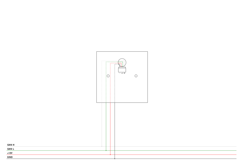
Connection diagram