
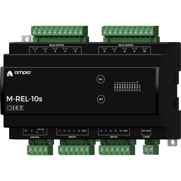
M-REL-10s: Module with ten relay outputs
M-REL-10s
Tags:
- Access Control,
- Air conditioning,
- Ampio CAN modules,
- Ampio Cloud,
- Analogue control,
- Central heating,
- CON Family,
- Dali,
- Dallas 18B20,
- DIM Family,
- Dimmer,
- DIN Rail modules,
- Display,
- DOT Family,
- Hotel,
- IN Family,
- Input Modules,
- Integrations,
- IP,
- Junction Box modules,
- KNX,
- LED Family,
- LED lights,
- Lights,
- Mobile App,
- Modbus,
- Node-red,
- OC Family,
- Open Collector Drivers,
- OUT Family,
- Output modules,
- OWA Lighting,
- OWA lighting bus modules,
- RDN Family,
- REL Family,
- Relay Outputs,
- RFID,
- RGBW Lights,
- Roller shutters and blinds,
- RS-232,
- RS-485,
- SATEL,
- Security,
- SENS Family,
- Sensors,
- SERV family,
- Touch panels,
- Wall Switch
Technical data
Technical data cont.
Dimensions
Environment
The image above is for illustration purpose only. The actual module may vary from the one presented here.
General features
Module M-REL-10s is a component of the Ampio system. Required voltage to power the module is 11 — 16V DC. The module is controlled via CAN bus.
The module has ten relay outputs, ten ground-detecting inputs and a 1-Wire interface. It also supports the functionality of a controller for the roller shutters and blinds’ drives.
Relay outputs
The module has SPST relay outputs that enable switching on resistive and inductive loads. The module relays are normally open. The table below shows the permissible operating parameters of the relays depending on the nature of the load.
| The nature of the load | Maximum supply voltage | Maximum long-term permissible current | Maximum load power |
|---|---|---|---|
| AC1: Resistive or moderately inductive AC loads | 250V AC | 16A | 2000VA |
| AC15: Inductive AC loads | 250V AC | 1.5A | 300VA |
| DC1: Resistive or moderately inductive DC loads | 30V DC | 16A | 400VA |
| DC13: Inductive DC loads | 30V DC | 2.5A | 30VA |
Roller shutter and blinds drives controller
As part of the module configuration, it is possible to activate the functionality of a roller shutter and a blind drives’ controller. This mode is intended for the control of devices powered by electric motors with a variable direction of movement and a limited movement range. For example, roller shutters and blinds’ drives. However, this mode can also be used in other devices of a similar nature, such as, e.g. gates.
In the controller mode for roller shutters and blinds’ drives, pairs of the device’s relay outputs work as a single compound output dedicated to controlling a single connected device.
The controller mode for roller shutters and blinds’ drive is designed to control devices with built-in limit switches that disconnect the drive’s power supply when the ends of the range of motion are reached.
In the primary operation mode of the relay outputs, they are controlled by switching on or off individual outputs. In the case of pairs of relays operating in the roller shutters and blinds’ drive controller mode, the control is performed by closing and opening commands or by setting the opening level. When it comes to blinds, it is also possible to set the position of slats.
During operation, the module estimates the state of the controlled device, i.e. the degree of opening and the position of slats (if applicable). This information is available within the building automation bus and is used internally to perform control in terms of the degree of opening or deflection angle of the slats.
A single pair of relays operating in a controller mode for roller shutters and blinds’ drives can only be connected to a single drive. Any other connection may result in incorrect operation of the device, as well as permanent damage to both, the module and the drive.
Ground detecting inputs
The module has inputs that go into the active state when they are shorted to ground. They can be used in the case of any devices with potential-free contact outputs, e.g. wall switches, reed switches, buttons, switches, etc. They can also be used for integration with devices with potential-free relay outputs or optocoupler outputs with a collector voltage greater than 12V.
Temperature sensors
The module is equipped with a 1-Wire interface connector that allows to connect up to 6 digital Dallas DS18B20 temperature sensors. The temperature measurement result is available for all devices operating within the building automation bus. It may turn out to be particularly useful for purposes related to temperature regulation, or to present the measurement result on touch panels and in a mobile application.
The total length of the 1-Wire bus cable to which the temperature sensors are connected cannot exceed 15m.
Typical application
- Switching on the lighting;
- control of motor devices;
- control of blinds and shutters;
- connecting classic light switches or other devices with potential-free contact outputs;
- integration with devices with potential-free relay outputs;
- integration with devices with optocoupler outputs;
- room temperature measurement.
Installation
The module is designed for mounting on a 35mm DIN rail. The module’s width is 160mm, 9 spaces/modules in DB. In order to start the module, it must be connected to the CAN bus. The bus of the Ampio system consists of four wires – two for power and two for communication between the modules.
In addition to the CAN bus interface, the device has five connectors with screw terminals. They allow for the connection of ten signal lines to ground-detecting inputs, ten loads to relay outputs, and up to 6 digital Dallas DS18B20 temperature sensors.
Device status LEDs
On the front of the module there are signalling LED indicators. The green LED with the label CAN indicates the status of communication on the CAN bus:
- one regular flash every 1 sec. – CAN bus communication is working properly,
- two regular flashes every 1 sec. – the module is not receiving information from other modules,
- three regular flashes every 1 sec. – the module cannot send information to the CAN bus;
Apart from the diode that indicates the status of the communication bus, on the front of the device there are also ten red diodes indicating the status of the open-collector outputs.
Manual control
On the front of the device there are two buttons labeled SEL and SET. They allow for manual control of the of the module’s relay outputs.
To activate the manual control mode, hold the SEL button for 3 seconds. When this mode is active, pressing the SEL button selects the relay output – the currently selected output is signaled by the flashing of its status diode. After selecting an output, it can be turned on or off by pressing the SET button.
In case of inactivity, the manual control mode turns off automatically. It is also possible to turn it off by holding the SEL button for 3 seconds.
Programming
The module is programmed with a special programmer, available for authorised technicians, and the Ampio Smart Home CAN configurator software. It allows you to modify the parameters of the module and define its behaviour in response to signals directly available to the module as well as general information coming from all devices present in the home automation bus.
If the functionality of the roller shutters and blinds’ drives controller is used, each connected device should be calibrated. The calibration is performed by defining the time parameters of full opening and closing, and the time parameters of the rotation of slats of the blinds (if applicable).
Module dimensions
Dimensions expressed in millimeters.

Connection diagram
