
M-CON-485-s: RS-485 integration module
M-CON-485-s
Tags:
- Access Control,
- Air conditioning,
- Ampio CAN modules,
- Ampio Cloud,
- Analogue control,
- Central heating,
- CON Family,
- Dali,
- Dallas 18B20,
- DIM Family,
- Dimmer,
- DIN Rail modules,
- Display,
- DOT Family,
- Hotel,
- IN Family,
- Input Modules,
- Integrations,
- IP,
- Junction Box modules,
- KNX,
- LED Family,
- LED lights,
- Lights,
- Mobile App,
- Modbus,
- Node-red,
- OC Family,
- Open Collector Drivers,
- OUT Family,
- Output modules,
- OWA Lighting,
- OWA lighting bus modules,
- RDN Family,
- REL Family,
- Relay Outputs,
- RFID,
- RGBW Lights,
- Roller shutters and blinds,
- RS-232,
- RS-485,
- SATEL,
- Security,
- SENS Family,
- Sensors,
- SERV family,
- Touch panels,
- Wall Switch
Dimensions
Technical data
Environment
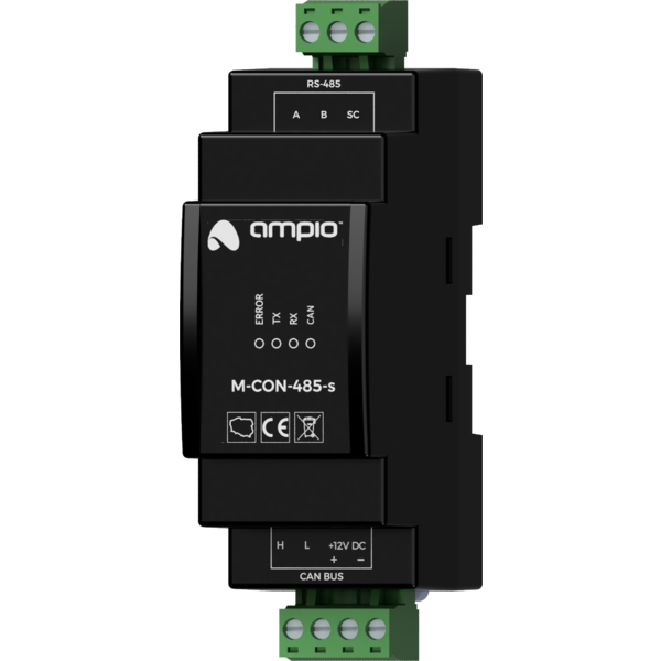
The image above is for illustration purpose only. The actual module may vary from the one presented here.
General features
Module M-CON-485-s is a component of the Ampio system. Required voltage to power the module is 11 — 16V DC. The module is controlled via CAN bus.
The module allows for the integration of devices equipped with an RS-485 communication interface with the Ampio home automation system.
Typical application
- Integration with alarm systems;
- integration with projectors and other display devices;
- integration with audio devices;
- integration with air conditioners and recuperators;
- integration with weather stations.
Installation
The module is designed for mounting on a 35mm DIN rail. The module’s width is 35mm, 2 spaces/modules in DB. In order to start the module, it must be connected to the CAN bus. The bus of the Ampio system consists of four wires – two for power and two for communication between the modules.
In addition to the CAN bus connector, the device has a connector that provides access to the A, B and SC lines of the RS-485 interface. The device connection diagram shows two variants of connection with a device being integrated. To determine whether an SC reference line connection is necessary, refer to the manual of the device being integrated.
Device status LEDs
On the front of the module there are signalling LED indicators. The green LED with the label CAN indicates the status of communication on the CAN bus:
- one regular flash every 1 sec. – CAN bus communication is working properly,
- two regular flashes every 1 sec. – the module is not receiving information from other modules,
- three regular flashes every 1 sec. – the module cannot send information to the CAN bus;
Apart from the communication bus status LED, there are three red LEDs on the front of the device:
- ERROR – indicates a communication error;
- TX – indicates that the device is sending data through the RS-485 interface;
- RX – indicates that the device is receiving data through the RS-485 interface.
The nature of the communication error depends on the specialised firmware variant loaded into the device.
Programming
The module is programmed with a special programmer, available for authorised technicians, and the Ampio Smart Home CAN configurator software. It allows you to modify the parameters of the module and define its behaviour in response to signals directly available to the module as well as general information coming from all devices present in the home automation bus.
Due to the complexity of the implemented functionalities and the specialised nature of firmware, the M-CON-485-s module is one of the few devices that is not updated automatically. Uploading a new version of the software is possible only manually, i.e. by selecting an appropriate file with the software update.
Unlike most Ampio system modules, the M-CON-485-s module software is specialised, i.e. depending on the intended use case, an appropriate firmware must be loaded to the device.
Specialised software is identified by a file name, the syntax of which is mostly consistent with the adopted nomenclature for Ampio devices’ update files. The only difference is that the last two digits of the software version define the purpose of the programme.
The M-CON-485-s module firmware’s file name takes the following form:
ampio_T25_P[PCB]_S[VER][TYP].amp
where:
[PCB]is the numerical identifier of the module’s hardware platform version,[VER]is the firmware version,[TYP]is the two-character firmware specialisation code.
The table below presents the available variants of the M-CON-485-s firmware specialisation:
| Specialisation code | Name | Description |
|---|---|---|
02 |
LE-03MP | Integration for the F&F LE-03MP energy meter. |
03 |
UNI-ONEWAY | General purpose one-way integrations – sending of arbitrary commands. |
04 |
ST-WEATH | Elsner P03/3-Modbus weather station. |
06 |
REK VALLOX | Integration with Vallox recuperators. |
07 |
UNI-MODBUS | Universal bidirectional Modbus integrator. |
08 |
JABLOTRON | Integration with the Jablotron alarm system. |
09 |
METEO | Integration with the Ampio M-METEO weather station. |
10 |
AMPIO-EKEY | Integration interface for ekey biometric products. |
ST-WEATH firmware variants
Elsner P03/3-Modbus weather stations available on the market implement the communication protocol in more than one way. Hence, there are two variants of specialised software for these stations. They are distinguished by the first character of the [VER] fragment of the module firmware’s file name.
- value
0or1– Modbus RTU; - value
2– ASCII protocol.
The specialised software files are delivered with the Smart Home CAN configurator software.
Module dimensions
Dimensions expressed in millimeters.

Connection diagram
