
M-OC-4s: Module with four OC outputs and an RGBW controller functionality
M-OC-4s
Tags:
- Access Control,
- Air conditioning,
- Ampio CAN modules,
- Ampio Cloud,
- Analogue control,
- Central heating,
- CON Family,
- Dali,
- Dallas 18B20,
- DIM Family,
- Dimmer,
- DIN Rail modules,
- Display,
- DOT Family,
- Hotel,
- IN Family,
- Input Modules,
- Integrations,
- IP,
- Junction Box modules,
- KNX,
- LED Family,
- LED lights,
- Lights,
- Mobile App,
- Modbus,
- Node-red,
- OC Family,
- Open Collector Drivers,
- OUT Family,
- Output modules,
- OWA Lighting,
- OWA lighting bus modules,
- RDN Family,
- REL Family,
- Relay Outputs,
- RFID,
- RGBW Lights,
- Roller shutters and blinds,
- RS-232,
- RS-485,
- SATEL,
- Security,
- SENS Family,
- Sensors,
- SERV family,
- Touch panels,
- Wall Switch
Technical data
Technical data cont.
Dimensions
Environment
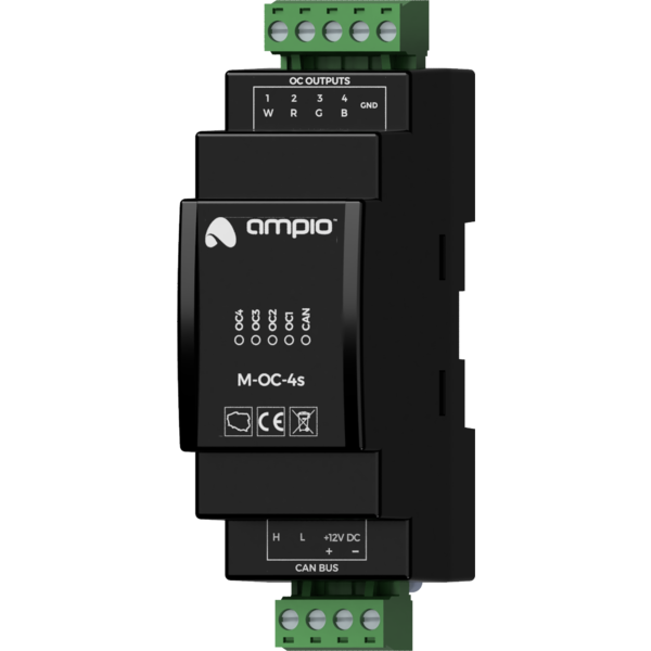
The image above is for illustration purpose only. The actual module may vary from the one presented here.
General features
Module M-OC-4s is a component of the Ampio system. Required voltage to power the module is 11 — 16V DC. The module is controlled via CAN bus.
The module has four OC outputs and supports the functionality of an RGBW lighting controller.
OC outputs
The module has open-collector outputs allowing for smooth control of resistive loads supplied with voltage of up to 40V DC. It is also allowed to control loads of moderate inductive nature, in particular relays. Control is performed by the method of pulse-width modulation (PWM). Internally, each of the outputs allows the connected line to be short-circuited to the module’s ground.
RGBW lighting
As part of the module’s configuration, it is possible to activate the functionality of the RGBW lighting controller. Nominally, each of the open-collector outputs is controlled independently. When the functionality is activated, the control is done by defining the colour and intensity of the light.
Typical application
- Smooth regulation of RGBW colour LED lighting;
- control of resistive loads supplied with voltages up to 40V DC, e.g.:
- LED lighting,
- piezoelectric buzzers,
- heating mats;
- control of relays.
Installation
The module is designed for mounting on a 35mm DIN rail. The module’s width is 35mm, 2 spaces/modules in DB. In order to start the module, it must be connected to the CAN bus. The bus of the Ampio system consists of four wires – two for power and two for communication between the modules.
In addition to the CAN bus connector, the device has a connector that allows for the connection of four resistive loads to open-collector outputs.
When using the open-collector outputs functionality, it should be borne in mind that the supply circuits of the connected loads are closed by the mass of the module. Therefore, it should be ensured that the mass of the device is connected to the mass of the power supply with a cable of appropriate thickness.
Device status LEDs
On the front of the module there are signalling LED indicators. The green LED with the label CAN indicates the status of communication on the CAN bus:
- one regular flash every 1 sec. – CAN bus communication is working properly,
- two regular flashes every 1 sec. – the module is not receiving information from other modules,
- three regular flashes every 1 sec. – the module cannot send information to the CAN bus;
Apart from the diode that indicates the status of the communication bus, on the front of the device there are also four red diodes indicating the status of the open-collector outputs.
Programming
The module is programmed with a special programmer, available for authorised technicians, and the Ampio Smart Home CAN configurator software. It allows you to modify the parameters of the module and define its behaviour in response to signals directly available to the module as well as general information coming from all devices present in the home automation bus.
Module dimensions
Dimensions expressed in millimeters.

Connection diagram
